How To Start A Sheet Metal Part In Solidworks 2015
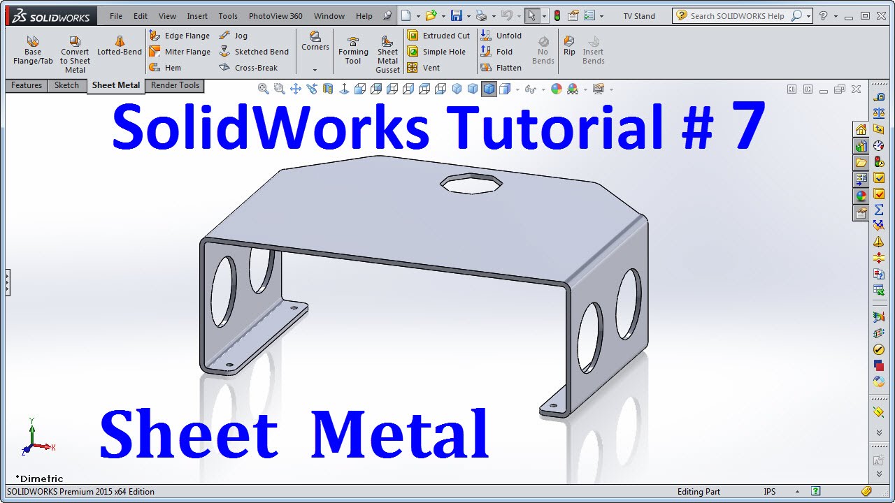
Solidworks 2015 Tutorial 007 Sheet Metal Youtube

Solidworks Sheet Metal Tutorial Youtube

New In Solidworks 2015 Update Training Sheet Metal

Solidworks Sheet Metal How To Start A Part Youtube

Solidworks Sheet Metal Normal Cuts And Simplify Bends Youtube

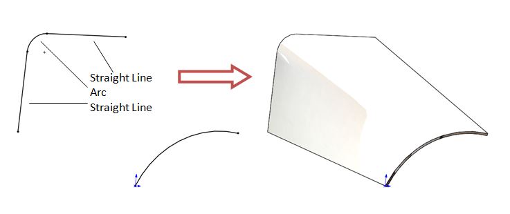
Solidworks Part Reviewer Complex Sheet Metal Tutorial
Create a part by sketching the part profile then extruding a thin feature part.
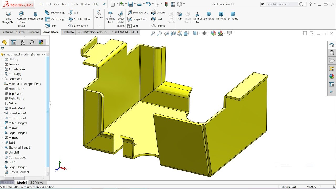
How to start a sheet metal part in solidworks 2015.

Solidworks Convert Sheet Metal Vs Make Sheet Metal Part Youtube
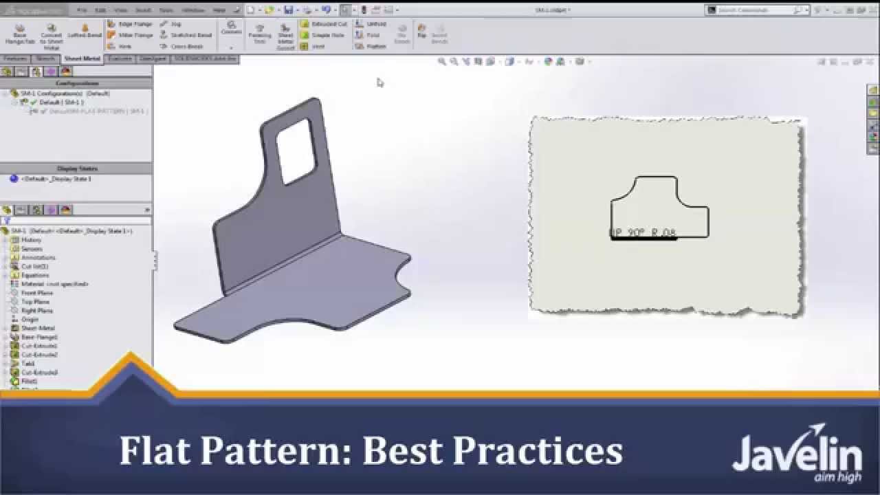
Solidworks Sheet Metal Tutorial Flat Pattern Best Practices Youtube
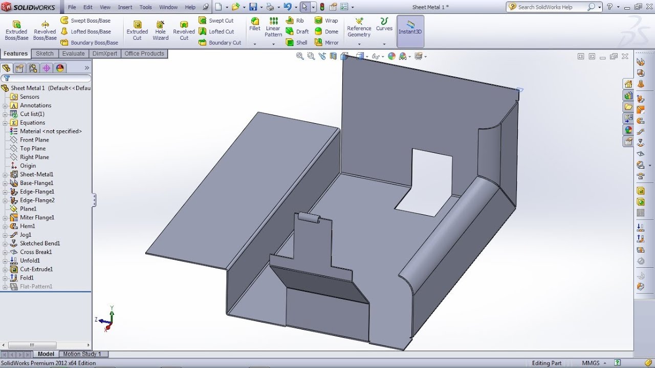
Solidworks Sheet Metal Tutorial For Beginner 1 Base Flange Tab Edge Flange Miter Flange Hem Youtube
Solidworks Tutorial Basics Of Sheet Metal Youtube
Source : pinterest.com
