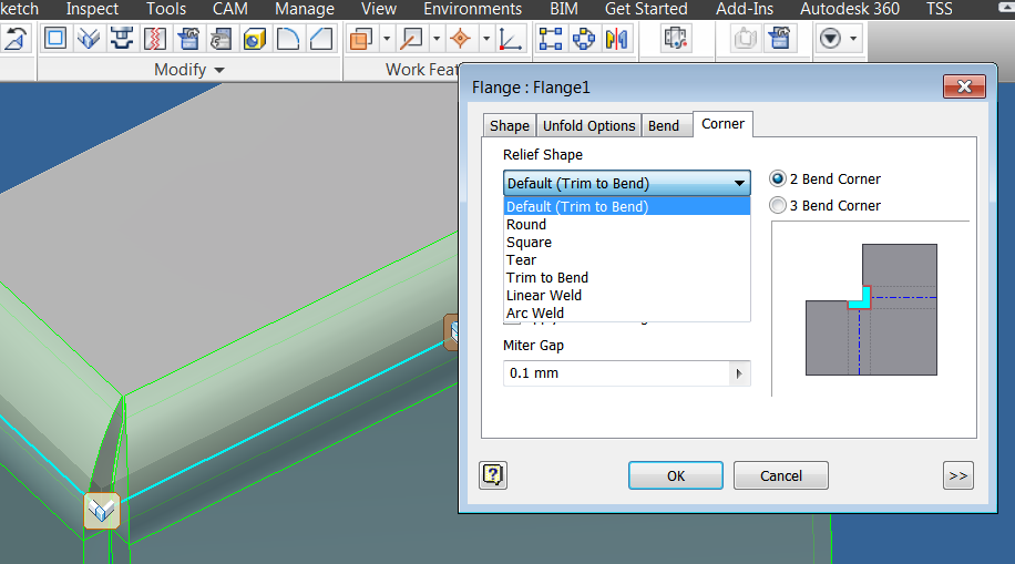
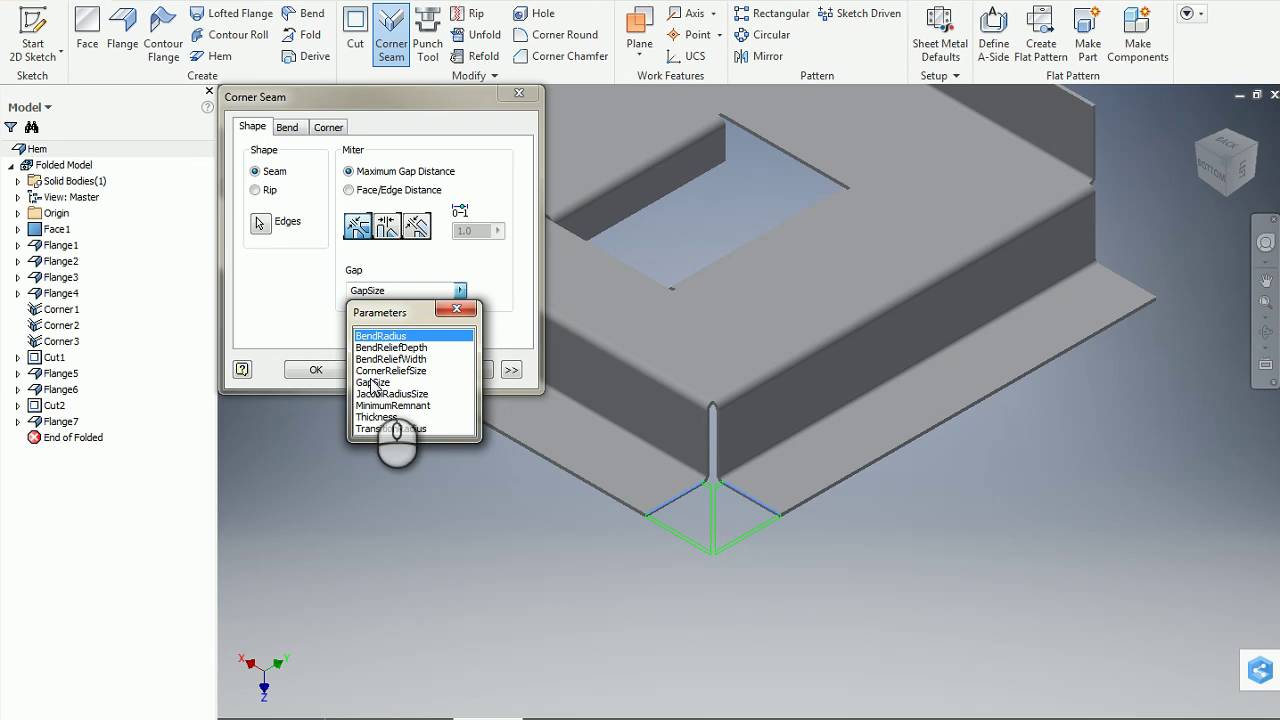
Select a model edge on each of two adjacent sheet metal faces.
How to weld a sheet metal corner shut in inventro.
Specify any of the following in the corner edit dialog box.
In the corner seam dialog box you can.
Accept the default seam type or select another of the three seam types.
On the ribbon click sheet metal tab modify panel corner seam.
Click the corner edit glyph for your selected corner.
To specify an overlap gap select overlap gap.
In part 22 of the autodesk inventor 101.
You can also use the real value edit drop down list on this field to specify a percentage of overlap with either the overlap or reverse overlap type enter a value from 0 to 1 for overlap gap.
Click the corner tab on the contour flange flange or corner seam dialog box.
To specify an overlap that differs from the value specified select overlap type in the corner edit dialog box.
For more information about corner reliefs see to work with corners in sheet metal feature.
Overrides default parameters that define how corners are relieved when a folded model is unfolded.
Inventor sheet metal corner relief options duration.
Change these parameters for individual features using the corner options tab.
Forget the larger 1 8 inch tungsten electrode and use a smaller one.
Laser weld relief shape.
To weld sheet metal with solid wires use electrode positive ep or reverse polarity.
To specify a corner relief.
The new laser weld corner relief terminates with a tangent arc and is more suitable for laser cut parts.
The default settings are specified in the sheet metal styles dialog box.
Tig welding sheet metal.
Don t attempt to weld thin materials like sheet metal with flux cored wires which put more heat into the base metal.
Shawn budden 4 797 views.
Inventor elbow modeling welding duration.
In this tutorial video we will learn sketch sh.